
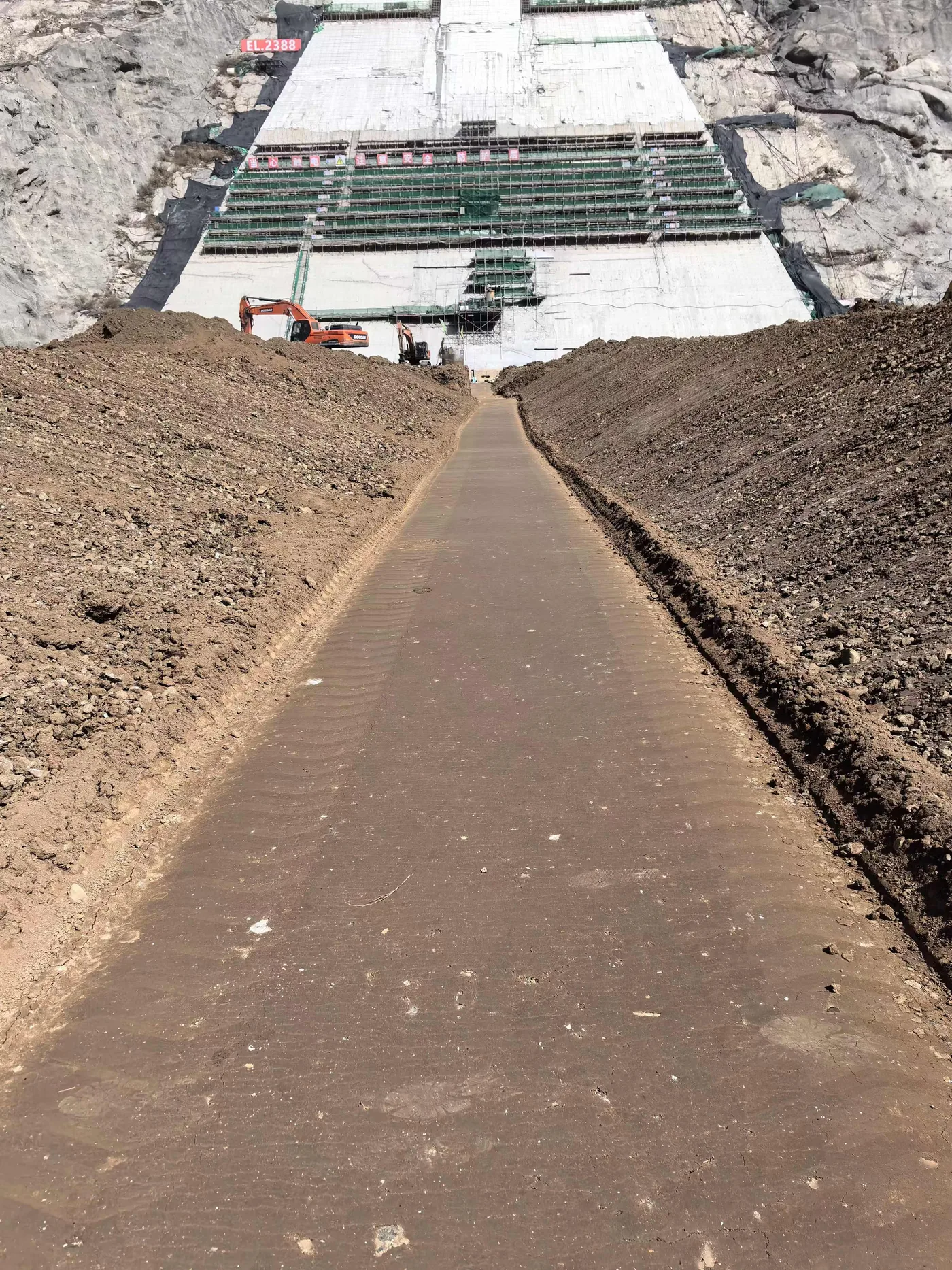
Track response as excavation advances
Excavation redistributes ground stresses and changes the loads acting on retaining structures. Engineers need measurements at depth to assess wall and soil response, alongside observations of nearby structures that may be affected by the work.
The retaining system, ground conditions and construction stages guide the instrument layout. A baseline taken before excavation allows later changes to be related to the work in progress.
What to measure
- Horizontal displacement of retaining structures and surrounding soil at depth
- Tilt of braces, columns and adjacent buildings
- Surface cracking and settlement observations
- Deformation trends through each excavation stage, assessed against project thresholds
Recommended instruments
The RT-1015 Lightweight In-Place Inclinometer uses a sensor string assembled on site for shallow-to-medium-depth boreholes. It is recommended for depths up to 60 m, with a maximum of 100 m; installations beyond 60 m require confirmation of power, communications and installation conditions.
The RT-1020 In-Place Inclinometer measures tilt over the long term at selected depths through an RS485 bus. RT-1070 Wireless Tiltmeters add local observations on supports or adjacent buildings.
Installation notes
Collect initial readings before excavation and use a consistent sampling schedule through the construction stages. Protect borehole heads, cables and brackets from plant movement and impacts. Check wireless-sensor fixings when reviewing an apparent change in tilt: a loose bracket can produce a change that does not represent structural movement.
Frequently asked questions
How do the RT-1015 and RT-1020 differ in an excavation installation?
Choose the RT-1015 when the design requires a connected borehole sensor string and places a priority on low transport weight and on-site assembly. Choose the RT-1020 when sensors are needed at selected depths on an RS485 bus. The required depth coverage and measurement spacing should guide the decision.