
A borehole head has been aligned correctly, yet the measured direction of movement does not match the field assessment. The discrepancy may also differ with depth.
Alongside the installation records and site observations, one possible cause needs attention: twist in the inclinometer casing grooves.
1. The problem is the direction assigned to each reading
Subsurface displacement monitoring needs to show both how much movement has occurred and its direction.
In a conventional arrangement that uses the casing grooves to orient the sensor, the measurement axes follow the grooves. If the grooves twist, the A/B displacement components can become mixed when interpreted in a common site coordinate system.
The deviation is hidden inside the borehole and may vary with depth. Aligning the casing at the top does not establish that every section below has the same orientation.
Twist may originate during manufacture, during casing installation and backfilling, or later as ground deformation changes the casing orientation. The practical question is how to maintain the sensor axes when the grooves turn.
2. Let the guide wheels follow the grooves
The shape-array installation separates guidance from orientation. The guide-wheel carrier accommodates the groove direction while the sensor string maintains its set orientation. At the end of installation, the string is aligned and locked at the borehole head.
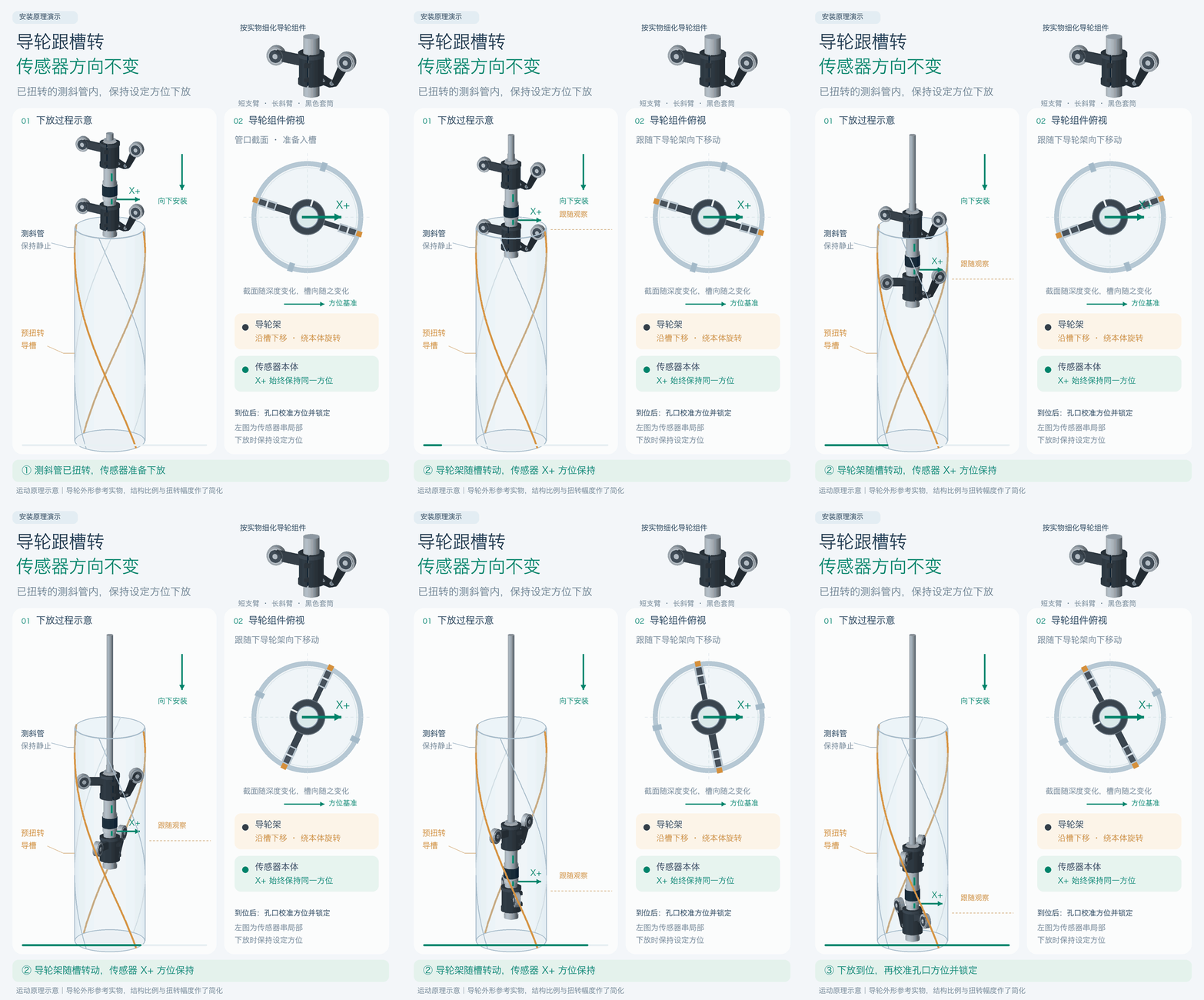
A rotating guide-wheel carrier. The wheels roll along the grooves during lowering. The carrier can also rotate around the sensor axis, allowing it to accommodate the groove direction independently of the sensor.
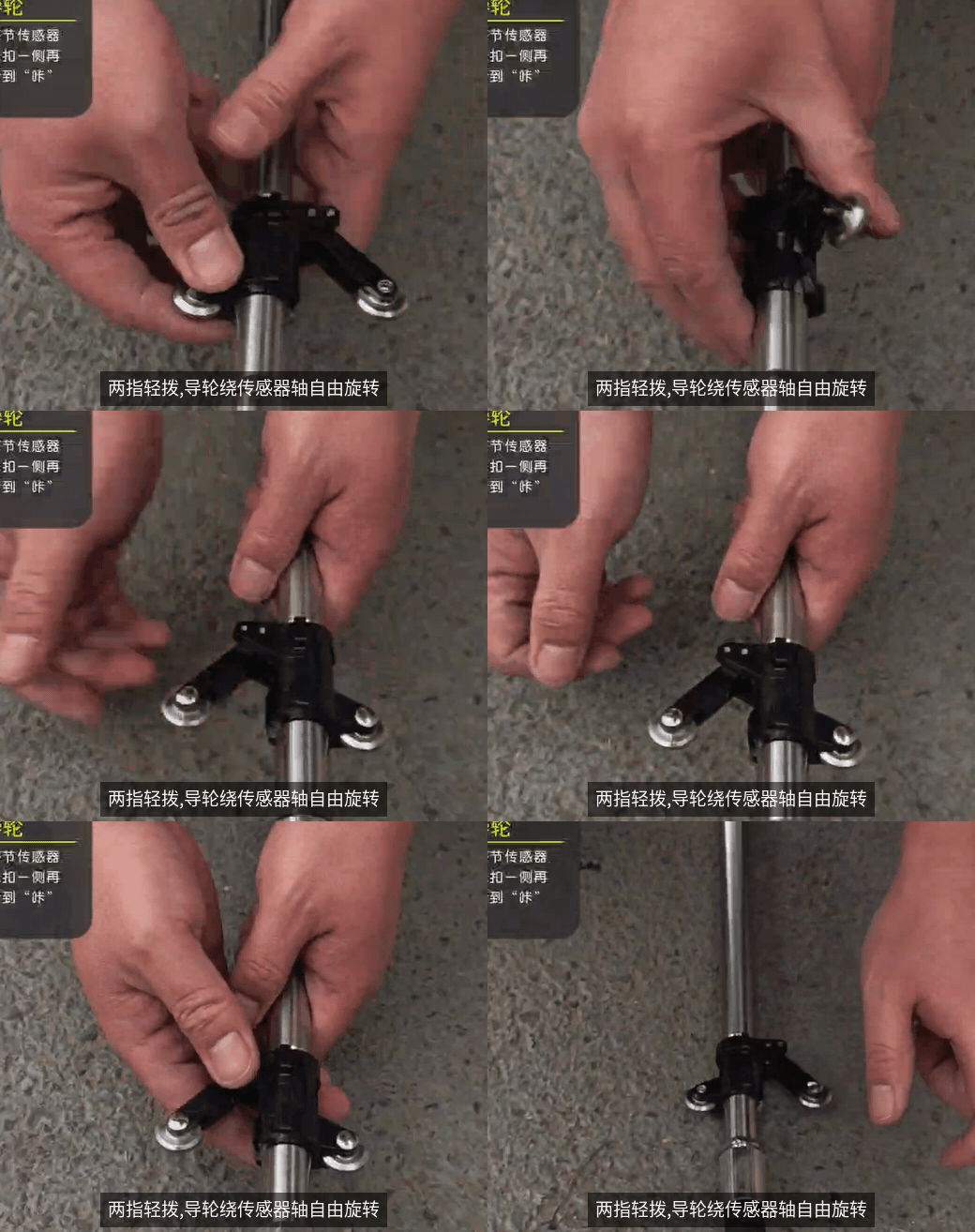
Connections between segments. The connections constrain relative twisting between sensors. Flexible joints accommodate bending while retaining the required torsional restraint, maintaining the orientation relationship along the string.
A reference at the borehole head. Maintain the specified orientation during lowering. Once the string is in place, check the X+ mark, align it to the required site direction, lock the head fixture and record the alignment.
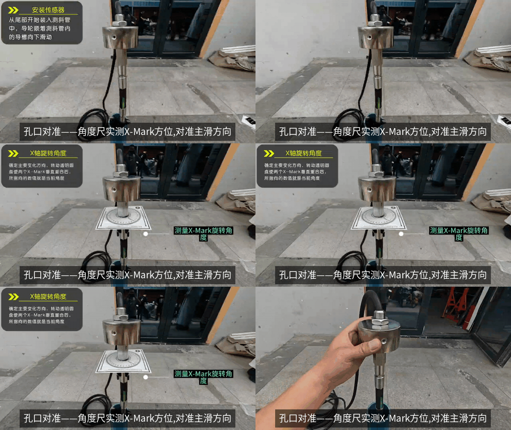
Maintaining orientation during lowering and checking it before locking the head are consecutive parts of the same installation procedure.
3. What this arrangement can address
The following applies when the guide-wheel carriers rotate freely, segment connections are secure, and the borehole head is correctly aligned and locked.
- Manufacturing spiral: the carriers follow the existing grooves, so groove orientation does not directly set sensor orientation.
- Twist introduced during casing installation: after the casing has stabilized, the final sensor orientation is established at the head rather than taken from the twisted grooves.
- Local twisting of casing sections during service: with a stable head reference, relative carrier rotation accommodates the changing grooves. The connections and head fixture work together to maintain the string orientation.
- Groove wear: the groove is no longer the orientation reference. Fixed installation also reduces wear from repeated insertion and withdrawal.
The purpose is to separate changes in groove direction from the sensor measurement direction. It applies to existing casing twist at installation and to local twisting inside the borehole during service, subject to the working conditions above.
4. Rotation of the whole borehole head needs an external check
A different situation occurs if the moving ground rotates in plan and carries the head, its fixture and the entire sensor string with it.
The orientation reference itself has then changed. Rotation of the guide-wheel carriers cannot keep the head pointing in its original site direction.
A sensor that measures tilt from gravity alone cannot directly identify rotation about the vertical axis. Tilt data alone therefore cannot automatically detect and correct this change in azimuth.
An order-of-magnitude estimate can still be useful. Assuming a small rotation and approximately rigid motion in plan, a smaller difference in movement between two laterally separated points implies a smaller rotation.
For points 50 m apart, a difference of 0.5 m in displacement along the same movement direction gives an estimated rotation of 0.57°, or about 0.6°. At the same spacing, a 3° rotation would correspond to a displacement difference of about 2.6 m.
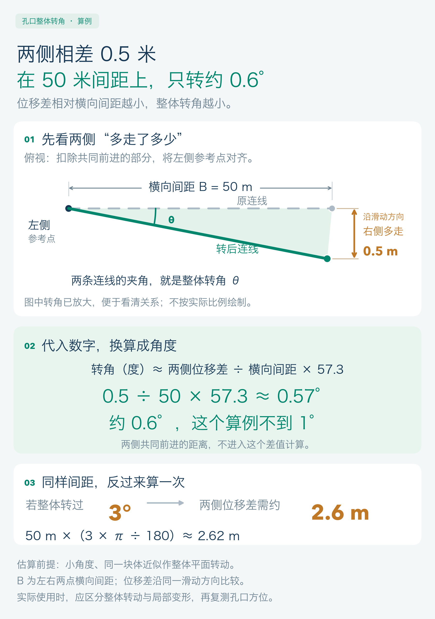
This estimate does not replace an orientation survey. It also requires distinguishing overall rotation from local deformation.
Record the head alignment at installation and recheck it against an external site reference as specified in the monitoring plan. If whole-string rotation is confirmed, use the surveyed angle to correct the coordinate direction or realign the installation according to the project procedure.
Jammed guide wheels, loose connections or severe casing restraint also require field investigation. The arrangement cannot automatically remedy those faults.
Related reading: Why can subsurface displacement be negative?. For an installation review, contact our team with the borehole depth, casing diameter and site conditions.