Build a station with selected sensors
Connect RT-1010, RT-1020, RT-1000DS and RT-1000CS sensors to bring displacement, tilt, ground acoustic and infrasound data into the acquisition terminal.

Data acquisition and system integration
Connect RT-1010, RT-1020, RT-1000DS ground acoustic and RT-1000CS infrasound sensors to the RT-2000 to build a monitoring station for your project. It supports external power and data output via 4G and an RJ45 Ethernet port. Built-in 256 Mbit storage supports historical data retention, retransmission and retrieval.
Benefits
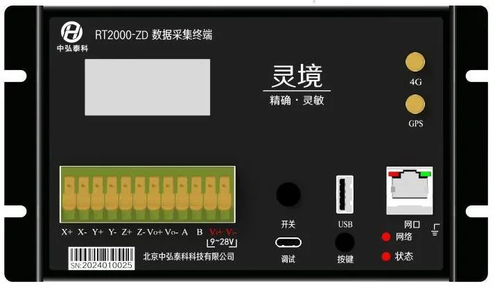
The product photo shows an existing terminal configuration; actual interfaces depend on the project.
Connect RT-1010, RT-1020, RT-1000DS and RT-1000CS sensors to bring displacement, tilt, ground acoustic and infrasound data into the acquisition terminal.
Built-in 256 Mbit storage retains historical monitoring data and supports data retransmission and retrieval.
Upload acquired data over 4G for remote viewing of monitoring data and device status. Configure acquisition and transmission settings for the project.
Output data through the RJ45 Ethernet port using TCP Client or MQTT Client to connect to the project's monitoring system.
The terminal supports an external supply; confirm the input voltage and wiring against the selected configuration.
Monitoring station
Connect displacement, tilt, ground acoustic and infrasound sensors to the RT-2000. Select the combination for the site and send the acquired data to a monitoring system.
Deep displacement and three-dimensional deformation.
Tilt measurements at selected borehole depths.
Ground acoustic waveforms and dominant frequency.
Pressure waveforms, dominant frequency and RMS sound pressure.
Connect selected sensors and configure acquisition for the monitoring task. Built-in 256 Mbit storage supports historical data retention, retransmission and retrieval.
External powerUpload field data for remote viewing.
Send data to the monitoring system using TCP Client or MQTT Client.
Applications
Specifications
Product support
Contact our technical team for current product information and project configuration.
Discuss your monitoring requirementsConnect RT-1010 Shape Arrays, RT-1020 in-place inclinometers, RT-1000DS ground acoustic sensors and RT-1000CS infrasound sensors in a station selected for the monitoring task. Confirm interfaces, sensor counts, protocols and power requirements for the project.
Use 4G transmission or output data through the RJ45 Ethernet port using TCP Client or MQTT Client. Select the method according to site connectivity and the receiving system.
Yes. The terminal has built-in 256 Mbit storage for historical monitoring data, with support for retransmission and retrieval.
RS485 defines the hardware interface. The terminal must also match each model's data protocol, communication settings and power requirements. Configure and commission these connections for the project.
The terminal can output data through its RJ45 Ethernet port using TCP Client or MQTT Client. The receiving system and communication settings are configured for the project.
The RT-2000 supports external power. The input voltage and wiring requirements must be confirmed for the selected configuration.
The photo shows an existing RT2000-ZD terminal configuration. The actual interfaces depend on the project configuration.