
Blast-vibration monitoring points in tunnels, mountainous areas and railway corridors may lack an external power supply. Access and installation time can also be limited. A field plan needs to cover mounting, communications and later data retrieval as well as the instrument itself.
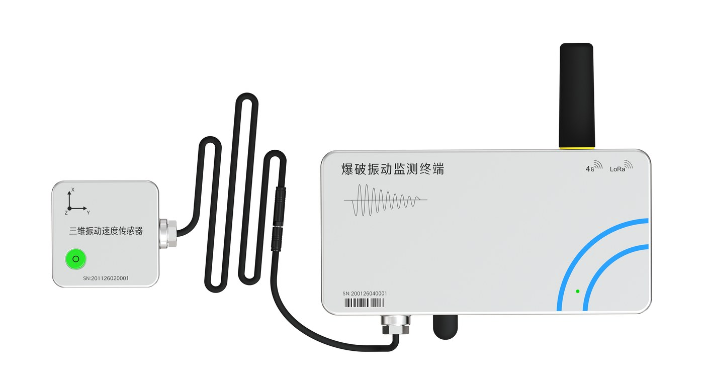
The RT-2001 Blast Vibration Monitoring Terminal uses an internal battery and a three-axis vibration-velocity sensor to record triggered events from blasting and piling. Power, event acquisition and data retrieval form part of the same field system.
Carry the system, then check the installation conditions
The terminal, sensor and installation accessories can be packed together for transport. An internal 95 Ah battery allows the terminal to operate independently, reducing the external power equipment required at the monitoring point.
Before entering the site, confirm the monitored object, measurement location, mounting surface and communications. Installation time depends on preparation and fixing conditions; allow time for sensor mounting, orientation checks and cable inspection.
Secure the terminal and couple the sensor correctly
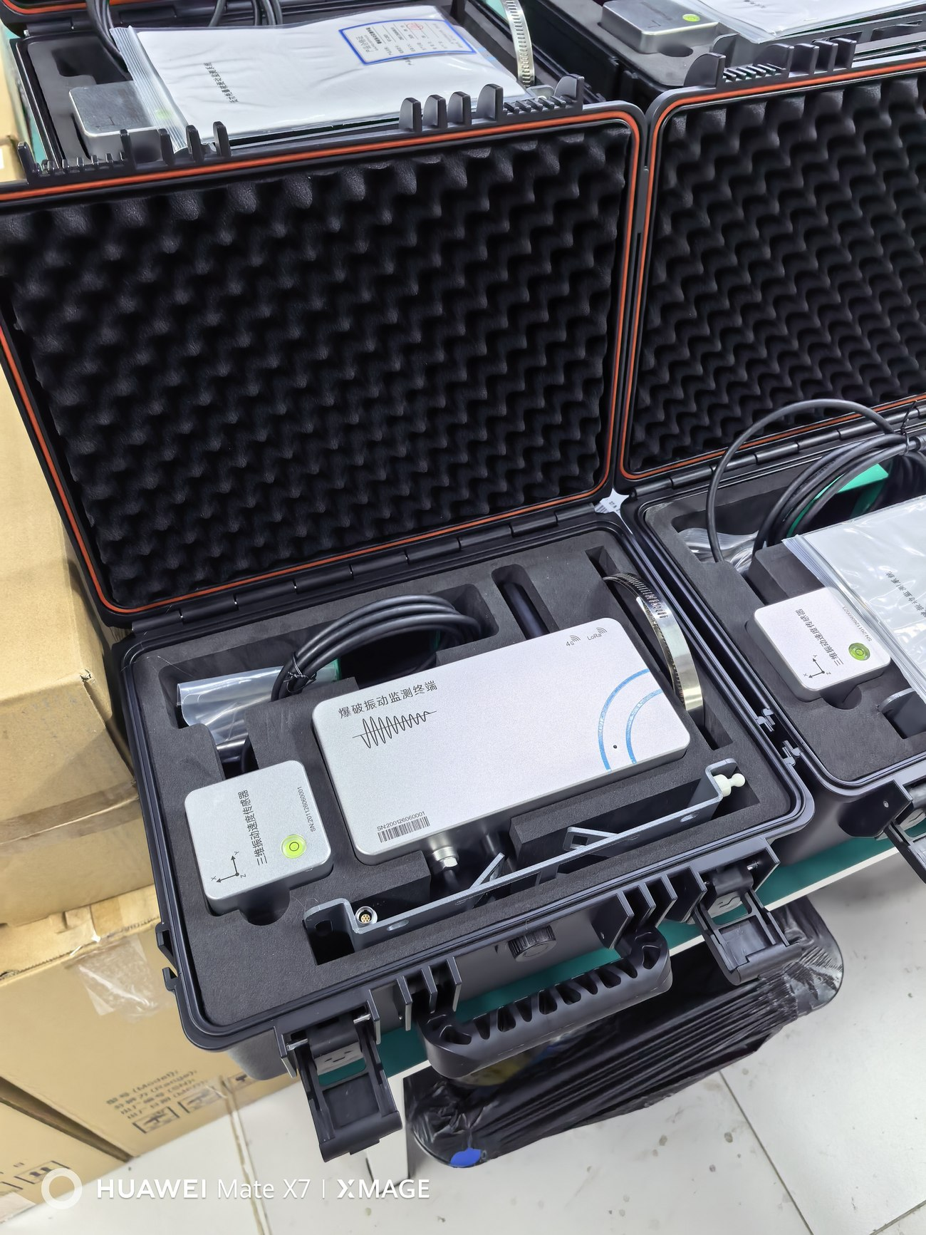
The terminal supports bracket or pole-clamp mounting. Choose the arrangement for the wall, existing pole and available space, and check the dimensions of the supplied fittings.
The sensor can be mounted on a wall, ground surface or tunnel crown. Check its direction markings and levelling requirements against the model’s installation instructions. Securely couple it to the monitored object, then connect the sensor cable to the terminal.
Internal power reduces external power wiring; the sensor still needs a correct connection to the terminal. Check the fixings, connectors and readings after installation, and record the point location and sensor orientation.
Low-power operation between triggered events
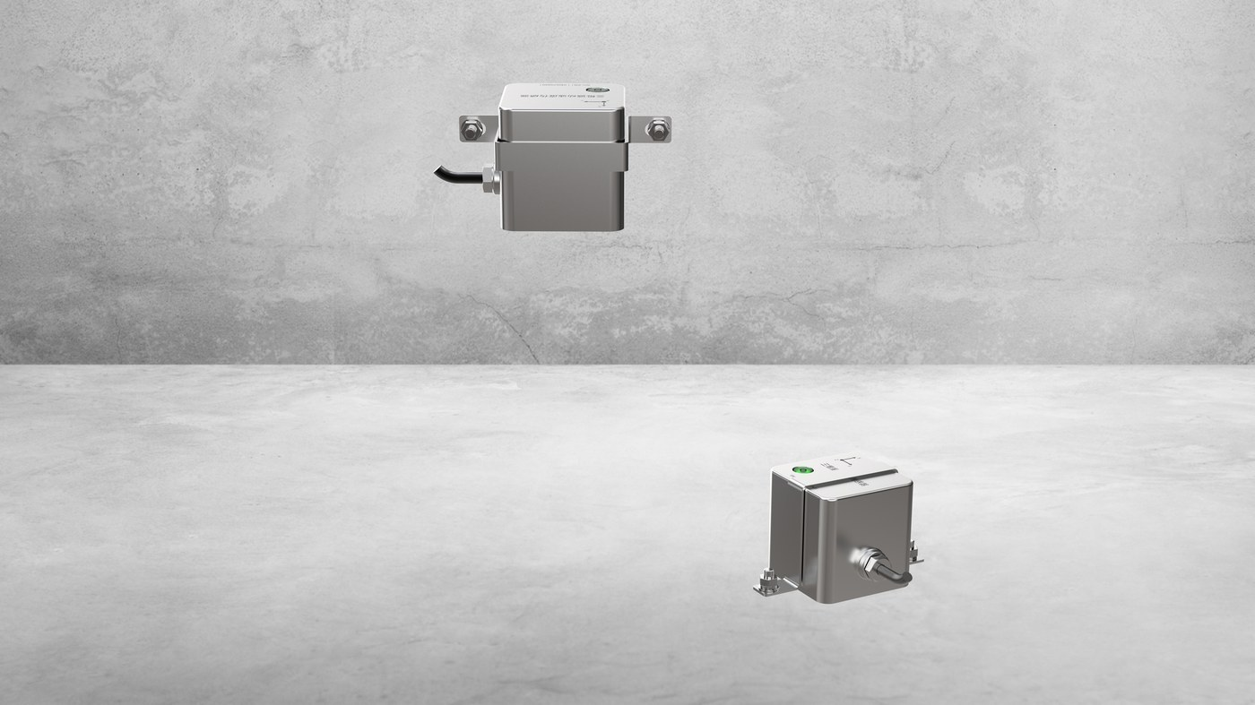
The terminal enters low-power mode when no event is triggered. A vibration trigger initiates event-waveform acquisition, with local storage.
This arrangement suits points focused on blasting or piling events. Match trigger conditions and acquisition settings to the monitoring objective, then use a test event to check the recording.
Battery service life depends on event frequency, communications and configuration. Confirm the operating conditions for each project.
Select 4G, optional LoRa Mesh or Bluetooth retrieval for the site
The device supports 4G and Bluetooth BLE 5.2. LoRa is optional.
Where 4G coverage is available, monitoring data can be uploaded to the platform. Without coverage, an Android app connects to the terminal over Bluetooth for parameter configuration, waveform viewing and historical-data download. Downloaded data can be synchronized to the platform after the phone reconnects to the internet.
Alongside power and mounting, define the communication method, retrieval procedure and archiving arrangement before deploying the point.
| Communication method | Site conditions | Route to the platform |
|---|---|---|
| Direct 4G upload | Stable 4G coverage at the monitoring point | RT-2001 → 4G network → server and platform |
| LoRa Mesh (optional) | No carrier coverage at the point; stable 4G coverage at the gateway | Acquisition node → configured RT-2001 relays → RT-2001 gateway → 4G → server and platform |
| Local Bluetooth retrieval | A technician can visit the point with the Android app | Stored records → Bluetooth → phone → platform once the phone is online |
Optional LoRa Mesh: relay event data from points without carrier coverage
The acquisition node connects to the three-axis vibration-velocity sensor and sends event data into the LoRa Mesh network. Configured RT-2001 relay nodes forward data between adjacent nodes. An RT-2001 gateway receives the data where stable 4G coverage is available and uploads it to the server.
Data direction: sensor → RT-2001 acquisition node → RT-2001 relay nodes → RT-2001 gateway → 4G → cloud platform. Select relay positions and quantities from field link tests. Spacing in the diagram does not represent radio range.
LoRa Mesh is an optional configuration. Confirm LoRa hardware, delivered firmware and node roles before deployment, then test the complete link, simultaneous triggers and end-to-end upload. The gateway still requires stable 4G coverage. Bluetooth retrieval uses an on-site phone to read local records and follows a different workflow.
See the RT-2001 communication options and LoRa Mesh diagram, and the data review, report and Android app interfaces.
Frequently asked questions
Can a point without 4G coverage upload data remotely?
An optional LoRa Mesh configuration can relay data to a gateway with stable 4G coverage. Verify the node links and gateway upload at the site. Local Bluetooth retrieval requires a technician to visit the point.
Is LoRa Mesh included in every RT-2001 configuration?
No. It is optional and requires compatible hardware, firmware and node configuration. Radio range, hop count and upload timing depend on the project and field tests.
Does internal battery power remove the sensor cable?
No. The battery powers the terminal. The three-axis vibration-velocity sensor still needs a correct cable connection and secure coupling to the monitored object.
Review the waveform and the device status
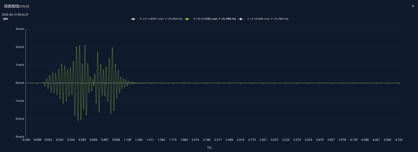
The platform provides vibration data, curves and device status, with remote configuration and firmware updates. Link each event to its monitoring point, timestamp, acquisition settings and waveform so it can be reviewed.
Assessment against project vibration-control requirements also depends on the monitored object, applicable standards and the agreed evaluation method.
Applications and preparation
The RT-2001 supports vibration monitoring for blasting, piling and nearby buildings, bridges, dams and historic structures. Both terminal and sensor have IP68 protection for field deployment.
Prepare the following when discussing a configuration:
- Type of work, monitored object and point locations;
- Mounting surface, available space and field protection;
- 4G coverage and any need for local Bluetooth retrieval or optional LoRa;
- Expected event frequency, data retrieval and maintenance arrangements.
See the RT-2001 product information, or contact our team by telephone or email to confirm a configuration for the site.